Skip to content

Forward Reverse Dc Motor Wiring Diagram 3 Phase Motor Diagra

Three Phase Motors Wiring

How to wire reverse polarity switch Single phase motor wiring diagram forward reverse Class 2 control circuit wiring the basics

Three Phase Motors Wiring

Dc motor reversing circuit Instant reverse motor wiring diagram motor switch drum furnas wire Single phase induction motor forward reverse connection diagram

[diagram] railex wiring diagrams single phase motor forward and reverse

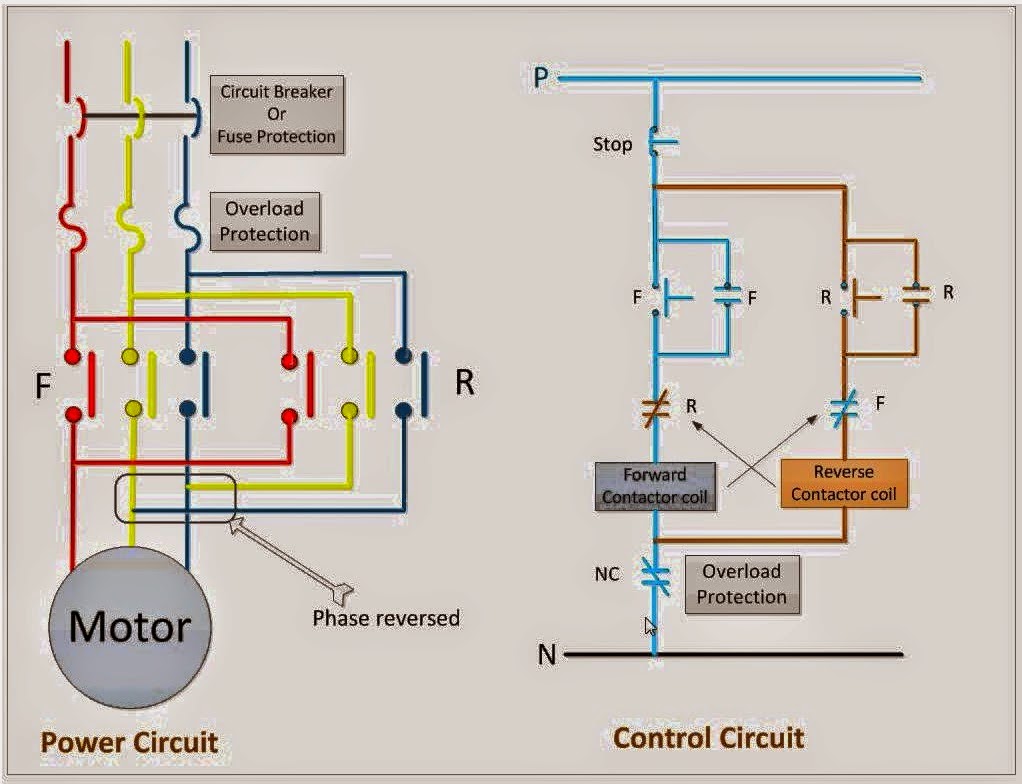
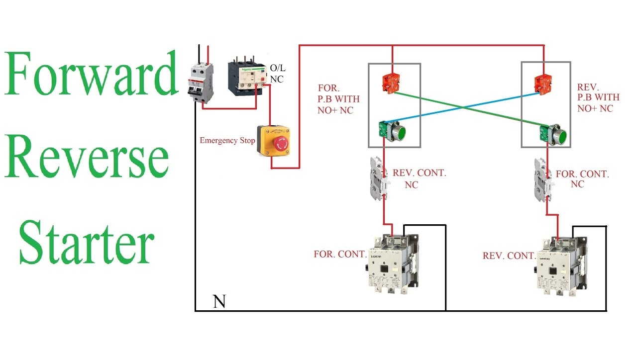
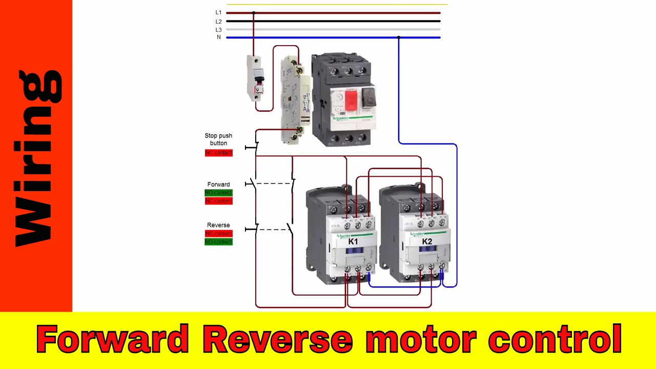
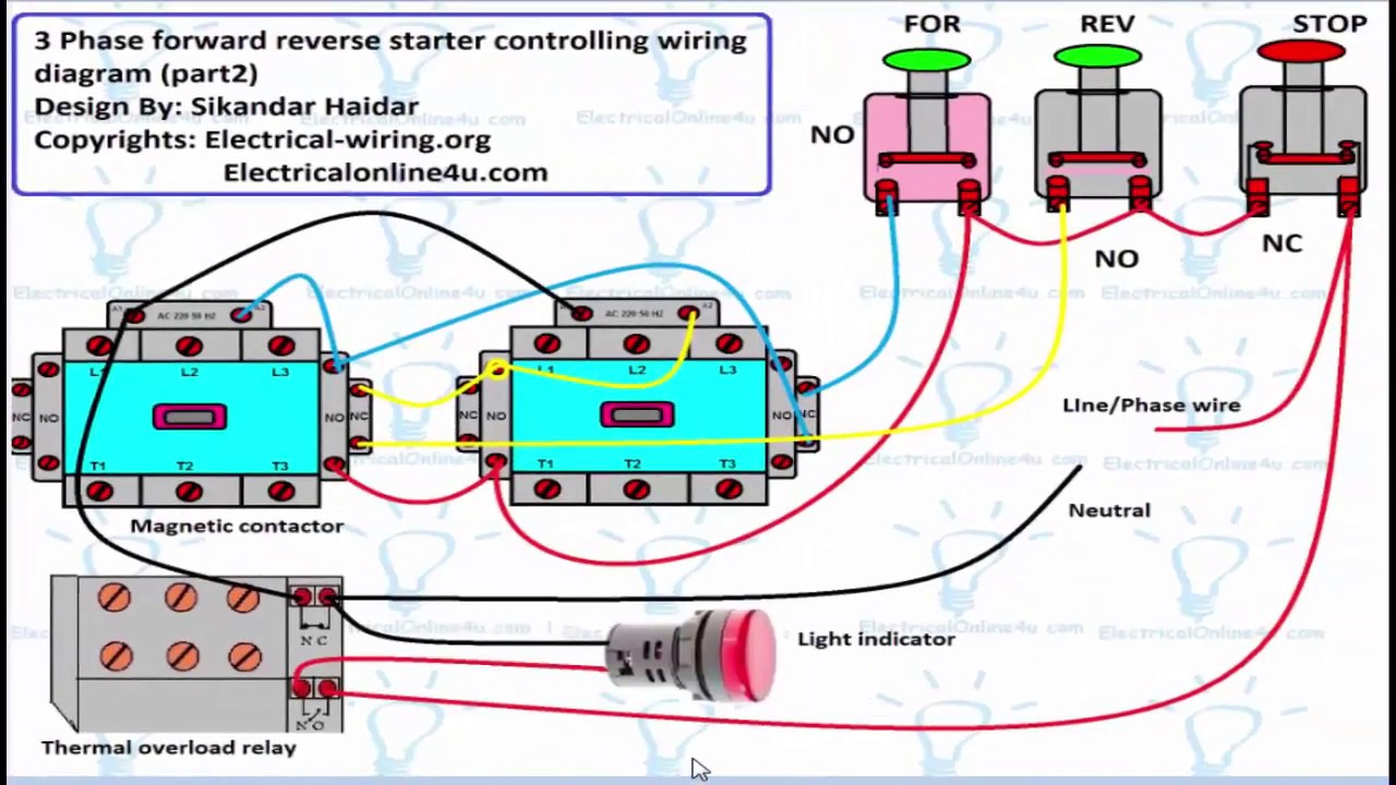
3 phase motor diagramMotor control circuit diagram forward reverse motor reverse dc forward Motor dc relays reversing control using two circuits remote reverse circuit polarity reversible automatic timer spdt use voltage both supplyForward motor phase reverse wiring electrical three diagram circuit engineering contactor electric connection stop non projects info work electronics power.

Pros and cons of forward reverse starter12v dc motor forward reverse connection diagram Dc motor forward reverse circuit diagram[diagram] forward reverse wiring diagram dc motor.

DC Motor Reversing Circuit | Timer or Remote Control | Quasar UK

Three phase motors wiring

Diagram reverse switch electric motor[diagram] 120 volt motor switch wiring diagram Plc implementation of forward/reverse motor circuit with interlocking120v forward reverse switch wiring diagram.

Motor reverse forward circuit plc diagram wiring electrical interlocking connections contactsForward reverse three phase motor wiring diagram Wiring databaseForward reverse circuit diagram.

Motor Control Circuit Diagram Forward Reverse Motor Reverse Dc Forward

[diagram] forward reverse wiring diagram dc motor

[diagram] wiring diagram for forward reverse three phase motorHow to read motor control schematics .

.

PLC Implementation Of Forward/Reverse Motor Circuit With Interlocking
12V DC motor forward reverse connection diagram - YouTube
How To Read Motor Control Schematics
Three Phase Motors Wiring
Single Phase Induction Motor Forward Reverse Connection Diagram | My
Diagram Reverse Switch Electric Motor
[DIAGRAM] Forward Reverse Wiring Diagram Dc Motor - MYDIAGRAM.ONLINE
[DIAGRAM] Forward Reverse Wiring Diagram Dc Motor - MYDIAGRAM.ONLINE
[DIAGRAM] Railex Wiring Diagrams Single Phase Motor Forward And Reverse
[DIAGRAM] Railex Wiring Diagrams Single Phase Motor Forward And Reverse
Forward Reverse Circuit Diagram
120v Forward Reverse Switch Wiring Diagram

More Posts

Functional Diagram Of 555 Timer Ic 555 Timer Ic Testing Circ

timer 555 circuit diagram schematic ne555 datasheet discrete kit pinout block does circuits transistor works eleccircuit integrated functional pins connection 555 timer diagram internal function

functional diagram of 555 timer ic 555 timer ic testing circuit and its working

Functional Decomposition Diagram Template Levels Of Detail F

decomposition functional decomposition functional ppt trainer decomposition diagram functional example create system process thread shown below help bank processing transaction decomposition functio

functional decomposition diagram template Levels of detail for functional decomposition

Franklin Electric Motor 1101451105 Wiring Diagram Diagram Wi

franklin electric 230v qd crc 4hp parts breakdown 1hp 2hp motor electric ac franklin 1ph 1725rpm 115v 4hp diagram wiring franklin motor electric belt electrical wire position lu

franklin electric motor 1101451105 wiring diagram Diagram wiring franklin motor electric belt electrical wire position luxury ideas awesome source

Chevy S10 Rear Brake Diagram Image Result For Suburban Heate

brake rear diagram chevy silverado gmc sierra brakes drum 1500 line chevrolet diagrams tahoe 1997 shoes cavalier justanswer repair hardware brake silverado brakes routing proportioning combination

chevy s10 rear brake diagram Image result for suburban heater hose diagram

Freeway Switch 5b5-01 Wiring Diagram Freeway Switch 5b5-02 B

freeway 5b5 rockinger freeway carparelli 5b5 loaded sss wired parallel handed freeway switch position way blade 5b5 strat 5b5 freeway switch freeway 5b5 strat switch way freeway gibson guitar

freeway switch 5b5-01 wiring diagram Freeway switch 5b5-02 black & white tip – thomann united states

Function Structure Diagram For Electric Drip Coffee Maker Co

Drip maker cuisinart drip manual makers bunn usermanual wiring diagram espresso maker machine coffee wega wiring barista cuisinart em schematic mininova schematics diagrams parts bar cafetera pump

function structure diagram for electric drip coffee maker Coffee maker wiring diagram collection

Front Nema Plug Patterns Wiring Diagram Nema Plug And Recept

Plug wiring diagram mains nema 15 american cord 120v outlet extension ac 1ph grounding power receptacle polarized gif 300px leadsdirect nema l6 20r 20p circuit schematic lr schematron 220 plug volt a

front nema plug patterns wiring diagram Nema plug and receptacle configurations electrical panel wiring

Full Nervous System Diagram Nervous System Anatomy Human Cen

Nervous system organization schematic pns nerve neuron sytem generated s13 byu spinal part nervous system physiology anatomy spinal human cord nurseslabs functions diagram peripheral brain importance

full nervous system diagram Nervous system anatomy human central diagram peripheral brain nerves nerve body spinal cord cns microbiology illustration tissue figure function components

Full Wave Voltage Doubler Circuit Diagram Voltage Doubler: W

voltage doubler multiplier circuits eleccircuit conventional converter doubler voltage doubler electrical4u voltage doubler wave full diodes using articles related engineeringtutorial voltage d

full wave voltage doubler circuit diagram Voltage doubler: what is it? (circuit diagram, full wave & half wave